Showing posts with label Begginer. Show all posts

Thursday, April 4, 2013

mxdt0003-Creating Microsoft Windows logo in 3ds Max Design

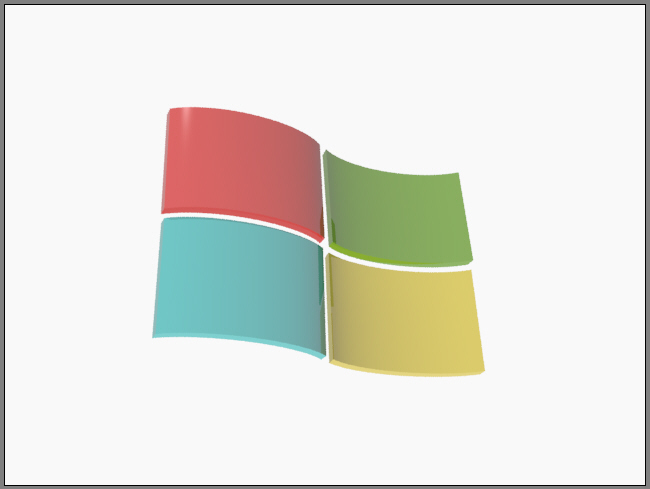
In this tutorial, you will learn how to create a Microsoft Windows logo in 3ds Max Design, as shown in Figure 1.

Figure 1  The Microsoft Windows logo

The following steps are required to complete this tutorial:
  1. Start Autodesk 3ds Max Design from the Start menu; the default Max Design interface is displayed, as shown in Figure 2.

    Figure 2  The default interface of 3ds Max Design
  2. Turn off the gridlines in Top, Front, and Left viewports by pressing the G key to make the objects visible.
  3. Choose Create > Shapes in the Command Panel and invoke the Arc tool from the Object Type rollout.
  4. Activate the Top viewport and create an arc, as shown in Figure 3.

    Figure 3  Creating an arc in the Top viewport
  5. You will now create a duplicate copy of the arc. To do so, select the arc in the Top viewport, press and hold the left mouse button and drag it down while holding the SHIFT key. Now release the left mouse button and the SHIFT key; the Clone Options dialog box is displayed. Select the Copy radio button in this dialog box and then choose the OK button; a duplicate copy of the arc is created, as shown in Figure 4.

    Figure 4  Creating a duplicate copy of the arc
  6. In the Top viewport, right-click on any arc and choose Convert To > Convert To Editable Spline from the cascading menu, as shown in Figure 5.

    Figure 5 Converting the arc into editable spline
  7. Choose the Modify tab in Command Panel. Next, choose the Vertex button to activate it in the Selection rollout.
  8. Expand the Geometry rollout and choose the Attach button. Next, select the other arc in the Top viewport and choose the Connect button.
  9. Select the one end of first arc and drag it to connect with the opposite end of second arc.
  10. Similarly, select the one end of second arc and drag it to connect with the opposite end of first arc. The two arcs are joined at their ends by the two lines, as shown in Figure 6.

    Figure 6  The two arcs joined at their ends by the two lines
  11. Choose the Vertex button again to deselect it. Next, select the arc in the Top viewport and name it as Arc01. It is now a single shape and not two separate arcs.
  12. With the Arc01 selected, select the Extrude option in Modifier List drop-down list to extrude the shape.
  13. In the Parameters rollout, set the value 900 in the Amount spinner; the shape is extruded, as shown in Figure 7.

    Figure 7  Extruding the shape
  14. Create a duplicate copy of the Arc01. To do so, select the Arc01 in the Top viewport and then press and hold the left mouse button along with SHIFT key. Drag it down and then release the left mouse button and the SHIFT key; the Clone Options dialog box is displayed. Make sure the Copy radio button is selected and name it as Arc02. Now, choose the OK button; the duplicate copy is created, as shown in Figure 8.

    Figure 8  Creating the duplicate copy of the shape
  15. Rotate the Arc02 180 degrees by using the Select and Rotate tool and align it with Arc01 in all viewports by using the Select and Move tool, as shown in Figure 9.

    Figure 9  Rotating the Arc02 and aligned it in all viewports
  16. Now, create a duplicate copy of the two shapes (Arc01 and Arc02) and drag them down, as shown in Figure 10.

    Figure 10  Creating a duplicate shape
  17. Invoke the Select and Move tool from the Main Toolbar and align the arc shape in all viewports to give a similar look just like Micorosoft Windows logo, as shown in Figure 11.

    Figure 11  Aligning the shapes in all viewports
  18. Finally, apply the material for every shape by using the Material Editor dialog box. The material you apply should match the colors of the real Microsoft Windows logo, as shown in Figure 12.

    Figure 12  Applying the color materials to the shape
  19. Invoke the Render Production tool from the Main Toolbar to render the scene. The final rendered image of the Microsoft Windows logo is shown in Figure 13.

    Figure 13  The final rendered image 
  20. Save the scene with the name Microsoft Windows logo.


Saturday, March 2, 2013

maxdt0001-Working in a new Customizing Viewport Layout

This feature will guide you how to customize viewport layouts in Autodesk 3ds Max Design. You can use this technique to customize your workspace as per your requirements. This is very great technique to segregate your work in different workspaces to reduce time and extra effort. In other words, you can easily switch between a number of viewports. You can use the viewport layout bar to manage your viewport layout settings. This bar is opened by default along with Autodesk 3ds Max Design interface.

To learn how to use this customization technique, follow the steps given below:
  • Start Autodesk 3ds Max Design; the default interface is displayed along with the viewport layout bar, as shown in Figure 1.

                                             Figure 1  The default interface displayed
  • Choose the Create a New Viewport Layout Tab icon from the viewport layout bar; the list of different in-built layouts is displayed in the Standard Viewport Layouts window, as shown in  Figure 2.
Figure 2  The list of in-built layouts displayed
  • Choose any one tab from the list of Standard Viewport Layouts window; the new workspace is displayed, as shown in Figure 3. Note that the new tab is also added in the viewport layout bar.

  Figure 3  The new workspace displayed
  • To rename this workspace, righ-click on the newly added tab; a flyout is displayed. In this flyout, enter the name as Workspace 1 in the Name text box, as shown in Figure 4. Press the ENTER key to confirm the changes. You can also delete this tab by clicking on the Delete Tab, refer to Figure 4.
Figure 4  Renaming the workspace

          Next, you will start working on this newly created workspace.
  • Choose Create > Geometry in the Command Panel. Make sure the Standard Primitive options is selected in the drop-down list, as shown in Figure 5.
                              Figure 5  The Command Panel
  • Invoke the Sphere tool from the Object Type rollout and create a sphere in any viewport, as shown in Figure 6.
Figure 6  Creating a sphere
  • Activate the Front viewport. Select the sphere by invoking the Select and Move tool. Hold the SHIFT key and drag the sphere to the right. Now, release the mouse and the SHIFT key; the Clone Options dialog box is displayed. Select the Copy radio button and enter 5 in the Number of Copies spinner, as shown in Figure 7. Choose the OK button; the five copies of sphere are created, as shown in Figure 8.
Figure 7  The Clone Options dialog box

Figure 8  Five copies of sphere created
  • Invoke the Select and Move, Select and Rotate, and Select and Uniform Scale tools from the Main Toolbar. Next, modify the shape of the spheres and align them in all viewports, as shown in Figure 9.
Figure 9  Modifying and aligning the spheres
  • Choose Group > Group from the menu bar; the Group dialog box is displayed. Enter the name Sphere01 in the Group name text box to group these spheres, as shown in Figure 10. 
Figure 10  The Group dialog box

         Next, you will create another sphere in the Perspective viewport and animate it in such a way so that it  
         will revolve round the Sphere01
  • Activate the Perspective viewport and create another sphere and scale down its size by using the Select and Scale tool.
  • Choose the Toggle Auto Key Mode button in the time controls to enter the animation mode, as shown in Figure 11.
Figure 11  The time controls

  • Enter 25 in the current frame spinner and press the ENTER key.
  • Invoke the Select and Move tool from the Main Toolbar and Selection Lock Toggle button on the status bar.
  • Activate the Top viewport and change the view from Wireframe to Shaded.
  • Select the sphere in the Top viewport and drag it in such a way so that it appears above the Shpere01 in the viewport, as shown in Figure 12.

Figure 12  Aligning sphere on the above of Sphere01

  • Enter 50 in the current frame spinner and press the ENTER key to move the next frame.
  • Move the sphere to the left of the Sphere01, as shown in Figure 13.

Figure 13  Aligning sphere on the left of Sphere01
  • Enter 75 in the current frame spinner and press the ENTER key to move to next frame. Alternatively, you can directly drag the Time Slider to frame 75.
  • Similarly, move the sphere below the Sphere01
  • Enter 100 in the current frame spinner and press the ENTER key.
  • Move sphere back to its original position, as shown in Figure 14.

Figure 14  Aligning sphere back to its original position

  • Choose the Toggle Auto Key Mode button to exit the animation mode.
  • Make sure the Perspective viewport is active and then choose the Play ANimation button to play the animation. The sphere will rotate around the Sphere01, as shown in Figure 15.

                                                        Figure 15  Sphere rotates around the Sphere01
  • Save the scene.